
Watch Video :- https://youtu.be/-itrPGl8TYQ
Optical fibers are circular dielectric wave-guides that can transport optical energy and information. They have a central core surrounded by a concentric cladding with slightly lower (by ≈ 1%) refractive index. Optical fibers are typically made of silica with index-modifying dopants such as GeO2. A protective coating of one or two layers of cushioning material (such as acrylate) is used to reduce cross talk between adjacent fibers and the loss-increasing microbending that occurs when fibers are pressed against rough surfaces. For greater environmental protection, fibers are commonly incorporated into cables. Typical cables have a polyethylene sheath that encases the fiber within a strength member such as steel or Kevlar strands.
Cross section view of an optical fiber.
Cross section view of a single fiber cable.
The Fiber as a Dielectric Wave-Guide: Fiber Modes
Since the core has a higher index of refraction than the cladding, light will be confined to the core if the angular condition for total internal reflectance is met. The fiber geometry and composition determine the discrete set of electromagnetic fields, or fiber modes, which can propagate in the fiber.
There are two broad classifications of modes: radiation modes and guided modes. Radiation modes carry energy out of the core; the energy is quickly dissipated. Guided modes are confined to the core, and propagate energy along the fiber, transporting information and power. If the fiber core is large enough, it can support many simultaneous guided modes. Each guided mode has its own distinct velocity and can be further decomposed into orthogonal linearly polarized components. Any field distribution within the fiber can be expressed as a combination of the modes. The two lowest-order guided modes of a circularly symmetrical fiber — designated LP01and LP11 — are illustrated in Figure 1.
When light is launched into a fiber, the modes are excited to varying degrees depending on the conditions of the launch — input cone angle, spot size, axial centration and the like. The distribution of energy among the modes evolves with distance as energy is exchanged between them. In particular, energy can be coupled from guided to radiation modes by perturbations such as microbending and twisting of the fiber — increasing the attenuation.

Figure 1a: LP01 Mode Distribution

Figure 1b: LP11 Mode DistributionFigure 1—Dispersion
Bandwidth Limitations
Bandwidth of an optical fiber determines the data rate. The mechanism that limits a fiber's bandwidth is known as dispersion. Dispersion is the spreading of the optical pulses as they travel down the fiber. The result is that pulses then begin to spread into one another and the symbols become indistinguishable. There are two main categories of dispersion, intermodal and intramodal.
Intermodal Dispersion
Intramodal Dispersion, sometimes called material dispersion, is a result of material properties of optical fiber and applies to both single-mode and multimode fibers. There are two distinct types of intramodal dispersion: chromatic dispersion and polarization-mode dispersion. As its name implies, intermodal dispersion is a phenomenon between different modes in an optical fiber. Therefore this category of dispersion only applies to mulitmode fiber. Since all the different propagating modes have different group velocities, the time it takes each mode to travel a fixed distance is also different. Therefore as an optical pulse travels down a multimode fiber, the pulses begin to spread, until they eventually spread into one another. This effect limits both the bandwidth of multimode fiber as well as the distance it can transport data.
Chromatic and Polarization-Mode Dispersion
The index of refraction varies depending upon wavelength. Therefore, different wavelengths will travel down an optical fiber at different velocities. This is known as Chromatic Dispersion.
This principle implies that a pulse with a wider FWHM will spread more than a pulse with a narrower FWHM. Dispersion limits both the bandwidth and the distance that information can be supported. This is why for long communications links it is desirable to use a laser with a very narrow line width. Distributed Feedback (DFB) lasers are popular for communications because they have a single longitudinal mode with a very narrow line width.
Polarization Mode Dispersion (PMD) is actually another form of material dispersion. Single-mode fiber supports a mode, which consists of two orthogonal polarization modes. Ideally, the core of an optical fiber is perfectly circular. However, the fact that in reality, the core is not perfectly circular, and mechanical stresses such as bending introduce birefringency in the fiber, causes one of the orthogonal polarization-modes to travel faster than the other, hence causing dispersion of the optical pulse.
Attenuation
Light power propagating in a fiber decays exponentially with length due to absorption and scattering losses. Attenuation is the single most important factor determining the cost of fiber optic telecommunication systems, as it determines spacing of repeaters needed to maintain acceptable signal levels.
In the near infrared and visible regions, the small absorption losses of pure silica are due to tails of absorption bands in the far infrared and ultraviolet. Impurities — notably water in the form of hydroxyl ions — are much more dominant causes of absorption in commercial fibers. Recent improvements in fiber purity have reduced attenuation losses. State-of-the-art systems can have attenuation on the order of 0.1 dB/km.
Scattering can couple energy from guided to radiation modes, causing loss of energy from the fiber. There are unavoidable Rayleigh scattering losses from small-scale index fluctuations frozen into the fiber when it solidifies. This produces attenuation proportional to l/λ4. Irregularities in core diameter and geometry or changes in fiber axis direction also cause scattering. Any process that imposes dimensional irregularities — such as microbending — increases scattering and hence attenuation.
Typical Spectral Attenuation in Silica
Figure 3: Dispersion
Figure 4: Typical Spectral Attenuation in Silica
Fiber Parameters
Numerical Aperture (NA)
Figure 5: Numerical Aperture
The Numerical Aperture (NA) of a fiber is defined as the sine of the largest angle an incident ray can have for total internal reflectance in the core. Rays launched outside the angle specified by a fiber's NA will excite radiation modes of the fiber. A higher core index, with respect to the cladding, means larger NA. However, increasing NA causes higher scattering loss from greater concentrations of dopant. A fiber's NA can be determined by measuring the divergence angle of the light cone it emits when all its modes are excited.
Qualitatively, NA is a measure of the light gathering ability of a fiber. It also indicates how easy it is to couple light into a fiber.
“V Number”
The Normalized Frequency Parameter of a fiber, also called the V number, is a useful specification. Many fiber parameters can be expressed in terms of V, such as: the number of modes at a given wavelength, mode cut off conditions, and propagation constants. For example, the number of guided modes in a step index multimode fiber is given by V2/2, and a step index fiber becomes single-mode for a given wavelength when V<2.405. Mathematically, V=2 π·NA·a/λ where “a” is the fiber core radius.
Fiber Preparation
Fiber Stripping
The outer sheath of fiber cables can be removed using electrical cable stripping tools, and scissors or a razor blade can trim the Kevlar strength member. However, the fiber coating must be very carefully removed to avoid damaging the fiber — surface flaws and scratches are the cause of most fiber failures. The coating can be removed using our Fiber Optic Strippers.
Fiber Termination
End surface quality is one of the most important factors affecting fiber connector and splice losses. Quality endfaces can be obtained by polishing or by using a fiber cleaver. Polishing is employed in connector terminations when the fiber is secured in a ferrule by epoxy. The following describes the popular connectors and their endface preparation styles.
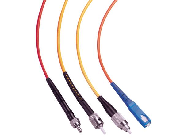
Fiber Optic Connector Types
SMA — due to its stainless steel structure and low-precision threaded fiber locking mechanism, this connector is used mainly in applications requiring the coupling of high-power laser beams into large-core multimode fibers. Typical applications include laser beam delivery systems in medical, bio-medical, and industrial applications. The typical insertion loss of an SMA connector is greater than 1 dB.
ST — the ST connector is used extensively both in the field and in indoor fiber optic LAN applications. Its high-precision, ceramic ferrule allows its use with both multimode and single-mode fibers. The bayonet style, keyed coupling mechanism featuring push and turn locking of the connector, prevents over tightening and damaging of the fiber end. The insertion loss of the ST connector is less than 0.5 dB, with typical values of 0.3 dB being routinely achieved. Drilled-out, metallic ST connectors, with insertion losses of >1 dB, are used with Newport's large-core (>140 µm) fibers.
FC — the FC has become the connector of choice for single-mode fibers and is mainly used in fiber-optic instruments, SM fiber optic components, and in high-speed fiber optic communication links. This high-precision, ceramic ferrule connector is equipped with an anti-rotation key, reducing fiber endface damage and rotational alignment sensitivity of the fiber. The key is also used for repeatable alignment of fibers in the optimal, minimal-loss position. Multimode versions of this connector are also available. The typical insertion loss of the FC connector is around 0.3 dB. Drilled-out, metallic FC connectors, having insertion losses of >1 dB, are being used with Newport's large-core (>140 µm) fibers.
SC — the SC connector is becoming increasingly popular in single-mode fiber optic telecom and analog CATV, field deployed links. The high-precision, ceramic ferrule construction is optimal for aligning single-mode optical fibers. The connectors' outer square profile combined with its push-pull coupling mechanism, allow for greater connector packaging density in instruments and patch panels. The keyed outer body prevents rotational sensitivity and fiber endface damage. Multimode versions of this connector are also available. The typical insertion loss of the SC connector is around 0.3 dB.
Connector Endface Preparation
Once the optical fiber is terminated with a particular connector, the connector endface preparation will determine what the connector return loss, also known as back reflection, will be. The back reflection is the ratio between the light propagating through the connector in the forward direction and the light reflected back into the light source by the connector surface. Minimizing back reflection is of great importance in high-speed and analog fiber optic links, utilizing narrow line width sources such as DFB lasers, which are prone to mode hopping and fluctuations in their output.
Flat Polish — a flat polish of the connector surface will result in a back reflection of about -16 dB (4%).
PC Polish — the Physical Contact (PC) polish results in a slightly curved connector surface, forcing the fiber ends of mating connector pairs into physical contact with each other. This eliminates the fiber-to-air interface, there by resulting in back reflections of -30 to -40 dB. The PC polish is the most popular connector endface preparation, used in most applications.
SPC and UPC Polish — in the Super PC (SPC) and Ultra PC (UPC) polish, an extended polishing cycle enhances the surface quality of the connector, resulting in back reflections of -40 to -55 dB and < -55dB, respectively. These polish types are used in high-speed, digital fiber optic transmission systems.
APC Polish — the Angled PC (APC) polish, adds an 8 degree angle to the connector endface. Back reflections of <-60 dB can routinely be accomplished with this polish.
Fiber Cleaving is the fastest way to achieve a mirror-flat fiber end — it takes only seconds. The basic principle involves placing the fiber under tension, scribing with a diamond or carbide blade perpendicular to the axis, and then pulling the fiber apart to produce a clean break. Our F-BK3 and FK11 fiber optic cleavers make the process especially quick and easy. It is wise to inspect fiber ends after polishing or cleaving.
Figure 6: Connector Endfaces
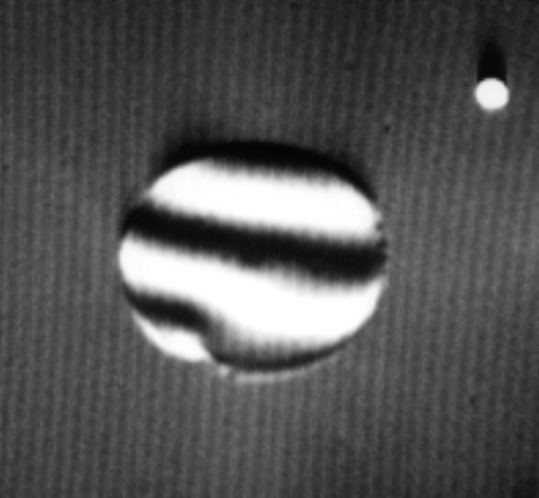
Figure 7: A typical F-BK3 cleave is clean, flat and perpendicular.
Coupling Light into Fibers
Good coupling efficiency requires precise positioning of the fiber to center the core in the focused laser beam. For multimode fibers, with their large cores, optical fiber positioners can achieve good coupling efficiency. Single-mode fibers require more elaborate couplers with submicron positioning resolution, like the ULTRAlign and 562F stainless steel positioners F-915 and F-1015 fiber optic couplers. These are also useful with Multi-mode fibers when maximum coupling efficiency is required.
The characteristics of the focused beam must match the fiber parameters for good coupling efficiency. For multimode fibers this is straightforward. General guidelines are:
The focused spot should be comparable to the core size.
The incident cone angle should not exceed the arcsine of the NA of the fiber (e.g. 23° for 0.2 NA and 35° for 0.3 NA).
To maximize coupling into a single-mode fiber, you must match the incident field distribution to that of the fiber mode. For example, the mode profile of the HE11 mode of a step index fiber can be approximated by a Gaussian distribution with a 1/e width w given by:
Where: d is the core diameter, and V is the “V-number.”
For our F-SV fiber, for which V = 2, the Gaussian width is approximately 28% larger than the core diameter, so the light should be focused to a spot size 1.28 times the core diameter at the fiber surface. For a Gaussian laser beam, the required beam diameter D incident upon focusing lens of focal length f to produce a focused spot of diameter w is D = 4λf/( πw). Given the laser beam waist and divergence, it's easy to determine the distance needed between the focusing lens and the laser to expand the beam to the required diameter.
The mode field diameter is now given to provide easier matching of lens to optical fiber for a Gaussian beam. A high numerical aperture lens must collimate the diverging output beam of a laser diode. Newport's F-L Series Diode Laser Focusing Lenses, are AR-coated for high transmittance at popular laser diode wavelengths and — with numerical apertures up to 0.5 — are useful for collimating or focusing.
Mode Scrambling and Filtering
Many multimode fiber experiments are sensitive to the distribution of power among the fiber's modes. This is determined by the launching optics, fiber perturbations, and the fiber's length. Mode scrambling is a technique that distributes the optical power in a fiber among all the guided modes. Mode filtering simulates the effects of kilometer lengths of fiber by attenuating higher-order fiber modes.
One scrambling technique is to splice a length of graded-index fiber between two pieces of step-index fiber — this ensures that the downstream fiber's core is overfilled regardless of launch conditions. Mode filtering can be achieved by wrapping a fiber several times around a finger-sized mandrel; bending sheds the high-order modes.
One way to achieve both scrambling and filtering is to introduce microbending to cause rapid coupling between all fiber modes and attenuation of high-order modes. One approach is to place a stripped section of fiber in a box filled with lead shot. A more precise way is to use Newport'. FM-1 Mode Scrambler. This specially designed tool uses a calibrated mechanism to introduce microbending for mode scrambling and filtering.
Figure 8: Launching conditions in a multimode optical fiber. (a) Overfilled (b) Underfilled
Figure 9: A schematic of Coupling of light into an optical fiber
Figure 10: Mode scrambler for optical fibers. The bends tend to couple out higher-order and radiation modes and to distribute the light into a distribution of modes that will remain stable over long distances.
Cladding Mode Removal
Some light is invariably launched into a fiber's cladding. Though cladding modes dissipate rapidly with fiber length, they can interfere with measurements. For example, the output of a single-mode fiber will not have a Gaussian distribution if light is propagating in the cladding. You can remove cladding modes by stripping a length of fiber coating and immersing the bare fiber in an index matching fluid such as glycerin.
Common Optical Parameters
The following is a list of common optical parameters associated with fiber optic components:
Port Configuration: Number of input ports x number of output ports. e.g. 2 x 2
Coupling Ratio: The ratio of the power at an output port to the launched power expressed in dB. e.g. -10log (P2/P1).
Isolation: The ratio of the power at an output port in the transmitted wavelength band to that in the extinguished wavelength band, expressed in dB.
Directivity: The ratio of the power returned to any other input port to the launched power, expressed in dB. e.g.-10log (P4/P1).
Bandwidth: The range of operating wavelengths over which performance parameters are specified.
Excess Loss: The ratio of the total power at all output ports to the launched power, expressed in dB. e.g. -10log [(P2+P3)/P1].
Uniformity: The difference between maximum and minimum insertion losses.
Extinction Ratio: The ratio of the residual power in an extinguished polarization state to the transmitted power, expressed in dB.
Return Loss: The ratio of the power returned to the input port to the launched power, expressed in dB. e.g.-10log (P5/P1).
Polarization-Dependent Loss (PDL): The maximum (peak-to-peak) variation in insertion loss as the input polarization varies, expressed in dB.
Fiber Optic Communications
The theoretical bandwidth of optical fiber transmission in the 1550 nm window alone is on the order of terabits. Current fiber optic systems have not even begun to utilize the enormous potential bandwidth that is possible.
There are two methods that are employed to achieve an increase in bandwidth. The first is known as Time Division Multiplexing or TDM. Multiple channels are transmitted on a single carrier by increasing the modulation rate and allotting a time slot to each channel. However, more sophisticated high-speed electronics, at both the transmitting and receiving ends of the communications link, are required when increasing the bit rate of a system. And as the bit rate increases, inherent modulation limiting characteristics of optical fibers become dominant. Chromatic and polarization mode dispersion cause pulse spreading, which affects the signal quality over longer transmission distances.
An alternate method for increasing the capacity of fiber optic communications systems is known as wavelength division multiplexing, or WDM. By this method, capacity can be increased by using more than one optical carrier (wavelength) on a single fiber. Therefore, adding a second transmitter and receiver to an optical fiber can double the bandwidth of that communications system. This method of increasing the capacity of an optical system has appeal for a variety of reasons. If a system were to increase in capacity using TDM alone, the existing transmitter and receiver would be replaced with a faster and more expensive transmitter/receiver pair. Using WDM, the existing transmitter and receiver do not need to be replaced. A second transmitter/receiver pair of a different wavelength is simply added. This is done by coupling, or multiplexing the output of the two lasers into a single fiber. At the receiving end, the two wavelengths are then separated, or demultiplexed, and each optical carrier is routed to its own receiver. For transmission systems using a 1310 nm laser, a second laser at 1550 nm is usually added. The reason for choosing these wavelengths is that they lie in the “windows” or ranges of least attenuation. This allows the signal to travel a longer distance.
The ITU (International Telecommunication Union) has proposed a set of closely spaced wavelengths in the 1550 nm window. This method of WDM is known as Dense Wavelength Division Multiplexing, or DWDM. These different wavelengths or channels, are spaced 100 GHz apart, which is approximately 0.8 nm. This set of channels is commonly known as the ITU-T grid, and is specified in frequency. The reason the 1550 nm window was chosen by the ITU is twofold: it is in one of the windows that has the smallest amount of attenuation; and it also lies in the band in which erbium doped optical amplifiers operate.
ITU-T DWDM Grid
| Channel Code | λ (nm) | Channel code | λ (nm) | Channel code | λ (nm) | Channel code | λ (nm) |
|---|---|---|---|---|---|---|---|
| 18 | 1563.05 | 30 | 1553.33 | 42 | 1543.73 | 54 | 1534.25 |
| 19 | 1562.23 | 31 | 1552.53 | 43 | 1542.94 | 55 | 1533.47 |
| 20 | 1561.42 | 32 | 1551.72 | 44 | 1542.14 | 56 | 1532.68 |
| 21 | 1560.61 | 33 | 1550.92 | 45 | 1541.35 | 57 | 1531.90 |
| 22 | 1559.80 | 34 | 1550.12 | 46 | 1540.56 | 58 | 1531.12 |
| 23 | 1558.98 | 35 | 1549.32 | 47 | 1539.77 | 59 | 1530.33 |
| 24 | 1558.17 | 36 | 1548.52 | 48 | 1538.98 | 60 | 1529.55 |
| 25 | 1557.36 | 37 | 1547.72 | 49 | 1538.19 | 61 | 1528.77 |
| 26 | 1556.56 | 38 | 1546.92 | 50 | 1537.40 | 62 | 1527.99 |
| 27 | 1555.75 | 39 | 1546.12 | 51 | 1536.61 | ||
| 28 | 1554.94 | 40 | 1545.32 | 52 | 1535.82 | ||
| 29 | 1554.13 | 41 | 1544.53 | 53 | 1535.04 |
Conceptual example of a fiber optic network.
The All-Optical Network
The all-optical network will be the next evolution in optical communications. Current DWDM systems are point-to-point links meaning that the signals have a single distinct starting and ending point. Research is being performed to help these networks evolve into fully configurable networks, which are not limited to fixed point-to-point links.
Transparency in the optical layer opens many possibilities for the future. Digital and analog transmission can occur on the same fiber. Different bit rates using different protocols will all travel together. Current research is being performed on reconfiguring an optical network in real time. Wavelength selective switching allows wavelengths to be routed through the network individually. Some of the applications of this are for network restoration and redundancy, which may reduce or entirely eliminate the need for an entire back up system to help the network recover from failures such as equipment malfunctions or fiber breaks. A reconfigurable network may offer bandwidth on demand to configure itself to optimize for traffic bottlenecks. The future may also include wavelength translation to convert traffic on one wavelength to another wavelength in the optical domain.
All optical switching is still in the research phase; however, researchers are looking for ways to create reliable, low loss switches with fast switching speeds. Investigation into the possibility of optical packet switching and other novel technologies are currently underway. The all-optical network may be just around the corner.
All optical switching is still in the research phase; however, researchers are looking for ways to create reliable, low loss switches with fast switching speeds. Investigation into the possibility of optical packet switching and other novel technologies are currently underway. The all-optical network may be just around the corner.
Photonic Crystal Fibers (PCFs)
Introduction
Endlessly Single-mode Photonic Crystal Fibers (PCF) are a subset of Photonic Crystals. The field of PCF was first explored in the latter half of 1990's and quickly evolved into a commercial technology. Photonic Crystal Fibers are generally divided into two main categories: Index Guiding Fibers that have a solid core, and Photonic Bandgap Fibers that have periodic microstructured elements and a core of low index material (e.g. hollow core). They can provide characteristics that ordinary optical fiber cannot, such as: single-mode operation from the UV to IR with large mode-field diameters, exceptionally high nonlinearity, numerical aperture (NA) ranging from very low to about 0.9, and optimized dispersion properties. Applications of PCFs are found in a wide range of research fields like spectroscopy, metrology, biomedicine, imaging, telecommunication, industrial machining, and military.
Fabrication and Characteristics
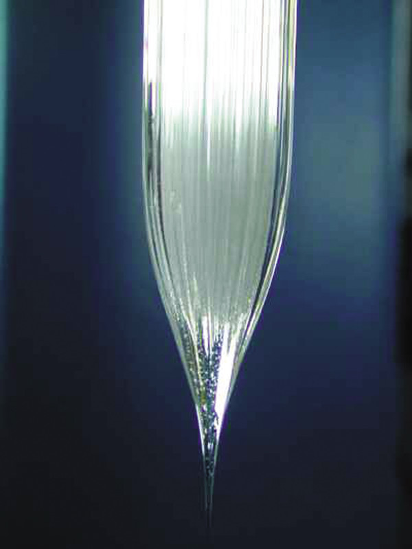
Figure 12: Close-up view of PCF preform
The typical starting point for manufacturing of an index guided PCF is an array of hollow capillary silica tubes bundled around a pure silica rod replacing the center capillary. For Photonic Bandgap (PBG) Fibers, one or more capillary tubes may simply be left out in the center of the preform in order to create a hollow 'defect' core. A sleeving tube surrounds the entire assembly that forms the preform. In a fiber draw tower, the preform is heated to around 2000°C and it is carefully pulled into fiber with the aid of gravity and pressure. Typical outer fiber diameter is 125 µm, but diameters from 80 to around 700 µm are routinely fabricated. This fiber maintains the structure of the preform, but now on a microscopic scale. Standard protective polymer coatings are applied to the fibers in order to improve handling characteristics.
The dispersion characteristics of PCFs can be manipulated to create fibers having zero, low, or anomalous dispersion at visible wavelengths. The dispersion can also be flattened. Combining these features with small mode field areas results in outstanding nonlinear fibers. By altering the pattern of air holes or the materials used, it is possible to manipulate other characteristics of PCFs, such as the single-mode cut-off wavelength, the NA, and the nonlinear coefficient. The design flexibility is very large, and designers can use many different, fascinating, and odd air hole patterns to achieve specific PCF parameters. The triangular arrangement of round air holes in the cladding is typically used to create single-mode fibers. Increasing the air-filling fraction in the cladding typically leads to multimode behavior. An elliptical core can create a highly birefringent fiber that is polarization maintaining.
Silica provides superior fiber performance for most applications with wavelengths between 200 and 2500 nm, but use of other materials can enhance specific parameters like nonlinearity or wave-guiding outside this spectral region. Furthermore, a long list of dopants can be added to silica. Doped silica is now used in a variety of fiber lasers and amplifiers; these could be combined with the unique capabilities of PCFs to provide even more useful devices. Coupling, splicing and connectorization of PCFs are other important issues because the fibers may have extreme parameters of mode field area and NA; coupling methods are in some cases very different from standard fiber methods. However, users may strip and cleave the PCFs with standard fiber tools. For laboratory use, the fibers are typically just cleaved and used with "open" ends. In such cases, it is important to avoid direct exposure of the fiber ends to any liquids since the capillary forces in the holes may draw the liquids several centimeters into the fiber, and thus disturb the wave-guiding properties.
PCFs can be spliced to standard fibers (and take advantage of the various connector schemes of such fibers), or the PCFs may be connectorized directly. Newport provides both PCFs spliced to standard fibers and directly connectorized on a semi-custom basis. Note that the mechanical strength of splices, the connectorized fiber core offset and connector-to-connector coupling are not always the same as standard fibers.
Directly connectorized fibers may furthermore provide beam expansion to lower the fiber end facet intensity and reduce the risk of damage at high power levels. Call Newport for more details.
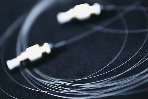
Figure 13: Most PCF fiber can be connectorized too. Call Newport for more information.
Newport's F-SM, and F-NL Series are index guided fibers. Similar to conventional fibers, index guiding PCFs transport light through a solid core by total internal reflection. The microstructured air-filled region in PCFs effectively lowers the index of the cladding – effectively creating a step-index optical fiber. The fiber behaves in many ways like standard step-index fibers, but it has a number of advantages. Index guiding PCFs are made of undoped silica that provides very low losses, sustains high powers and temperature levels, and may withstand nuclear radiation. Depending on PCF design, the air in the cladding may be utilized to yield fibers with extremely low or extremely high index steps.
Figure 14: Schematic of an index guided PCF
Figure 15: Cross section of triangular cladding PCF
A typical cross section of an index guided PCF is shown in Fig 14 and 15. The PCF consists of a triangular lattice of air holes where the core is defined by a “missing” air hole. The pitch is labeled Λ, and measures the period of the hole structure (the distance between the centers of neighboring air holes). The hole size is labeled d, and measures the diameter of the holes. Some PCFs have a cladding refractive index that exhibits a strong wavelength dependence. Together with the inherently large design flexibility, PCFs allow for a whole range of novel properties to be explored. Such properties include endlessly single-mode fibers (F-SM Series), extremely nonlinear fibers and fibers with anomalous dispersion in the visible wavelength region (F-NL Series). A unique feature of PCFs is that a single fiber may support single-mode operation over a wavelength range from around 300 nm to beyond 2000 nm – even for large mode field areas (of several hundred µm2). This allows PCFs to be utilized for transmission of very high powers with high beam quality without running into nonlinear or damage barriers (several hundred Watts for CW operation). On the other hand, the highly nonlinear fibers made as single-mode fibers have extremely small mode field areas (typically around 3 µm2) and confine light to the core region efficiently.
Figure 16: Cross section of air-clad PCF
Compared to standard fiber technology, where the light is guided using solid glasses with different refractive indices, several new properties may be realized using PCF technology. For example:
- Fibers that are single-mode in a very broad spectral range (in principle all wavelengths)
- Very small mode sizes may be obtained (down to approx. 1 µm)
- Very large mode sizes may be obtained (up to 25 µm or larger)
- Zero dispersion wavelengths below 1300 nm is possible (down to approx. 600 nm)
- Exceptionally large birefringence close to 10-2 can be realized
- Very high numerical apertures up to 0.9 may be obtained
Hence, PCFs are ideally suited for applications requiring large non-linearities, broadband operation with single-mode guidance, large mode areas, light collection from a large solid angle, etc.
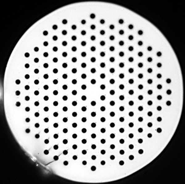
Figure 17: Large Mode Area fiber (F-SM Series)
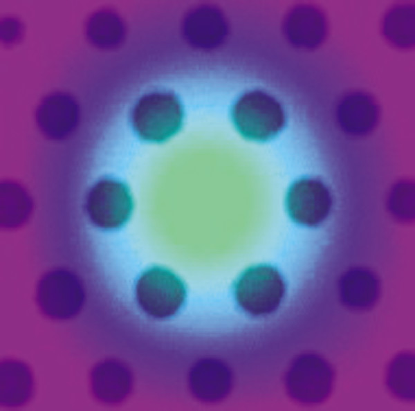
Figure 18: Near field image of F-SM fiber at 1550 nm
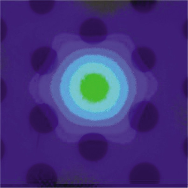
Figure 19: Mode structure of F-SM20 fiber
Formation of broad continuous spectra through propagation of short femto or picosecond-range high power pulses through nonlinear media (also known as supercontinuum generation, or SCG) was first observed in 1970 and has since then been studied extensively in many different materials. The term supercontinuum does not cover a specific phenomenon but rather a plethora of nonlinear effects leading to considerable spectral broadening of optical pulses and thereby potentially octave-spanning output. The involved nonlinear effects depend on the dispersion in the material and count effects like self-phase modulation (SPM), Raman Scattering, phase matching and solitons.
Results on SCG in PCFs have previously been presented with pumping in the anomalous dispersion regime or at the zero-dispersion wavelength in both the visible and the infrared wavelength range. Most experiments utilize femtosecond pumping as this results in spectacularly broad spectra. Picosecond pumping yields more narrow spectra, but does so with far cheaper laser sources and is therefore commercially interesting.
Although SCG can be observed in a drop of water given enough pumping power, PCFs are ideal media for SCG as the dispersion can be designed to facilitate continuum generation in a specific region. In this way, it is possible to convert light to both higher and lower wavelength, just like super wide spectra covering more than an octave is achievable at previously unthinkable low power levels.
Practical Supercontinuum Tips
SCG-800 and SCG-800-CARS are ideal in generating supercontinuum using an ultrafast laser. When coupling light from a femtosecond laser into a crystal fiber, a number of issues regarding pulse distortion must be addressed to achieve the optimum performance. In this section, we discuss the precautions taken to couple light from a Ti:Sapphire Laser into a 1.7 µm core PCF. The first issue to be addressed is the 4% reflection from the fiber surface, which can lead to a distortion of the pulse train and in severe cases will stop the laser from mode-locking. Cleaving the fiber at an angle can minimize back reflections. However, we recommend that the problem be avoided by the use of a Faraday Isolator. Coupling out a small portion of the beam and directing it to Newport's PulseScout Autocorrelator allows for real-time monitoring of the pulse width and beam quality.
The femtosecond pulses are easily coupled into the fiber through standard microscope objectives. Magnifications of 40x and 60x provide good results. Aspheric ball lenses can also be used, but as these are not achromatic, they should not be used with short femtosecond pulses due to the broad spectral range of these pulses. The dispersion in the microscope objective should be compensated using a precompensating prism or grating compressor in order to launch the shortest possible (i.e. highest intensity) pulse into the fiber. The diameter of the laser beam should match the aperture of the microscope objective. This is easily achieved with a standard telescope.
Nonlinear effects are inherently very sensitive to variations in the input power, thus a very stable mount is needed. To avoid displacement of the fiber end due to thermal, acoustic and other unwanted effects, the fiber should be mounted as close to the end as possible. Gluing the fiber to the mount, or using a connectorized fiber, can create further stability.
If polarization-maintaining fibers are used, the polarization axis of the linearly polarized femtosecond pulses should coincide with one of the principal axes in the fiber. The relative orientation of the axes can be controlled either by a half-wave plate or by rotating the fiber. To find the principal axis one can measure the polarization state of the output and rotate the half-wave plate or the fiber until the output is linearly polarized. When using the above described alignment procedure, coupling efficiencies well above 40% are routinely achieved.
Geometry and Strength of F-SM Fibers
In order to screen the fibers from microbending losses, the F-SM Series are fabricated with large cladding diameters for the largest core sizes. All fibers have a single-layer acrylate coating, and have been proof tested with a tension of at least 5.0 N.Optical fibers are circular dielectric wave-guides that can transport optical energy and information. They have a central core surrounded by a concentric cladding with slightly lower (by ≈ 1%) refractive index. Optical fibers are typically made of silica with index-modifying dopants such as GeO2. A protective coating of one or two layers of cushioning material (such as acrylate) is used to reduce cross talk between adjacent fibers and the loss-increasing microbending that occurs when fibers are pressed against rough surfaces. For greater environmental protection, fibers are commonly incorporated into cables. Typical cables have a polyethylene sheath that encases the fiber within a strength member such as steel or Kevlar strands.
Cross section view of an optical fiber.
Cross section view of a single fiber cable.
The Fiber as a Dielectric Wave-Guide: Fiber Modes
Since the core has a higher index of refraction than the cladding, light will be confined to the core if the angular condition for total internal reflectance is met. The fiber geometry and composition determine the discrete set of electromagnetic fields, or fiber modes, which can propagate in the fiber.
There are two broad classifications of modes: radiation modes and guided modes. Radiation modes carry energy out of the core; the energy is quickly dissipated. Guided modes are confined to the core, and propagate energy along the fiber, transporting information and power. If the fiber core is large enough, it can support many simultaneous guided modes. Each guided mode has its own distinct velocity and can be further decomposed into orthogonal linearly polarized components. Any field distribution within the fiber can be expressed as a combination of the modes. The two lowest-order guided modes of a circularly symmetrical fiber — designated LP01and LP11 — are illustrated in Figure 1.
When light is launched into a fiber, the modes are excited to varying degrees depending on the conditions of the launch — input cone angle, spot size, axial centration and the like. The distribution of energy among the modes evolves with distance as energy is exchanged between them. In particular, energy can be coupled from guided to radiation modes by perturbations such as microbending and twisting of the fiber — increasing the attenuation.
Figure 1a: LP01 Mode Distribution
Figure 1b: LP11 Mode DistributionFigure 1—Dispersion
Bandwidth Limitations
Bandwidth of an optical fiber determines the data rate. The mechanism that limits a fiber's bandwidth is known as dispersion. Dispersion is the spreading of the optical pulses as they travel down the fiber. The result is that pulses then begin to spread into one another and the symbols become indistinguishable. There are two main categories of dispersion, intermodal and intramodal.
Intermodal Dispersion
Intramodal Dispersion, sometimes called material dispersion, is a result of material properties of optical fiber and applies to both single-mode and multimode fibers. There are two distinct types of intramodal dispersion: chromatic dispersion and polarization-mode dispersion. As its name implies, intermodal dispersion is a phenomenon between different modes in an optical fiber. Therefore this category of dispersion only applies to mulitmode fiber. Since all the different propagating modes have different group velocities, the time it takes each mode to travel a fixed distance is also different. Therefore as an optical pulse travels down a multimode fiber, the pulses begin to spread, until they eventually spread into one another. This effect limits both the bandwidth of multimode fiber as well as the distance it can transport data.
Chromatic and Polarization-Mode Dispersion
The index of refraction varies depending upon wavelength. Therefore, different wavelengths will travel down an optical fiber at different velocities. This is known as Chromatic Dispersion.
This principle implies that a pulse with a wider FWHM will spread more than a pulse with a narrower FWHM. Dispersion limits both the bandwidth and the distance that information can be supported. This is why for long communications links it is desirable to use a laser with a very narrow line width. Distributed Feedback (DFB) lasers are popular for communications because they have a single longitudinal mode with a very narrow line width.
Polarization Mode Dispersion (PMD) is actually another form of material dispersion. Single-mode fiber supports a mode, which consists of two orthogonal polarization modes. Ideally, the core of an optical fiber is perfectly circular. However, the fact that in reality, the core is not perfectly circular, and mechanical stresses such as bending introduce birefringency in the fiber, causes one of the orthogonal polarization-modes to travel faster than the other, hence causing dispersion of the optical pulse.
Attenuation
Light power propagating in a fiber decays exponentially with length due to absorption and scattering losses. Attenuation is the single most important factor determining the cost of fiber optic telecommunication systems, as it determines spacing of repeaters needed to maintain acceptable signal levels.
In the near infrared and visible regions, the small absorption losses of pure silica are due to tails of absorption bands in the far infrared and ultraviolet. Impurities — notably water in the form of hydroxyl ions — are much more dominant causes of absorption in commercial fibers. Recent improvements in fiber purity have reduced attenuation losses. State-of-the-art systems can have attenuation on the order of 0.1 dB/km.
Scattering can couple energy from guided to radiation modes, causing loss of energy from the fiber. There are unavoidable Rayleigh scattering losses from small-scale index fluctuations frozen into the fiber when it solidifies. This produces attenuation proportional to l/λ4. Irregularities in core diameter and geometry or changes in fiber axis direction also cause scattering. Any process that imposes dimensional irregularities — such as microbending — increases scattering and hence attenuation.
Typical Spectral Attenuation in Silica
Figure 3: Dispersion
Figure 4: Typical Spectral Attenuation in Silica
Fiber Parameters
Numerical Aperture (NA)
Figure 5: Numerical Aperture
The Numerical Aperture (NA) of a fiber is defined as the sine of the largest angle an incident ray can have for total internal reflectance in the core. Rays launched outside the angle specified by a fiber's NA will excite radiation modes of the fiber. A higher core index, with respect to the cladding, means larger NA. However, increasing NA causes higher scattering loss from greater concentrations of dopant. A fiber's NA can be determined by measuring the divergence angle of the light cone it emits when all its modes are excited.
Qualitatively, NA is a measure of the light gathering ability of a fiber. It also indicates how easy it is to couple light into a fiber.
“V Number”
The Normalized Frequency Parameter of a fiber, also called the V number, is a useful specification. Many fiber parameters can be expressed in terms of V, such as: the number of modes at a given wavelength, mode cut off conditions, and propagation constants. For example, the number of guided modes in a step index multimode fiber is given by V2/2, and a step index fiber becomes single-mode for a given wavelength when V<2.405. Mathematically, V=2 π·NA·a/λ where “a” is the fiber core radius.
Fiber Preparation
Fiber Stripping
The outer sheath of fiber cables can be removed using electrical cable stripping tools, and scissors or a razor blade can trim the Kevlar strength member. However, the fiber coating must be very carefully removed to avoid damaging the fiber — surface flaws and scratches are the cause of most fiber failures. The coating can be removed using our Fiber Optic Strippers.
Fiber Termination
End surface quality is one of the most important factors affecting fiber connector and splice losses. Quality endfaces can be obtained by polishing or by using a fiber cleaver. Polishing is employed in connector terminations when the fiber is secured in a ferrule by epoxy. The following describes the popular connectors and their endface preparation styles.
Fiber Optic Connector Types
SMA — due to its stainless steel structure and low-precision threaded fiber locking mechanism, this connector is used mainly in applications requiring the coupling of high-power laser beams into large-core multimode fibers. Typical applications include laser beam delivery systems in medical, bio-medical, and industrial applications. The typical insertion loss of an SMA connector is greater than 1 dB.
ST — the ST connector is used extensively both in the field and in indoor fiber optic LAN applications. Its high-precision, ceramic ferrule allows its use with both multimode and single-mode fibers. The bayonet style, keyed coupling mechanism featuring push and turn locking of the connector, prevents over tightening and damaging of the fiber end. The insertion loss of the ST connector is less than 0.5 dB, with typical values of 0.3 dB being routinely achieved. Drilled-out, metallic ST connectors, with insertion losses of >1 dB, are used with Newport's large-core (>140 µm) fibers.
FC — the FC has become the connector of choice for single-mode fibers and is mainly used in fiber-optic instruments, SM fiber optic components, and in high-speed fiber optic communication links. This high-precision, ceramic ferrule connector is equipped with an anti-rotation key, reducing fiber endface damage and rotational alignment sensitivity of the fiber. The key is also used for repeatable alignment of fibers in the optimal, minimal-loss position. Multimode versions of this connector are also available. The typical insertion loss of the FC connector is around 0.3 dB. Drilled-out, metallic FC connectors, having insertion losses of >1 dB, are being used with Newport's large-core (>140 µm) fibers.
SC — the SC connector is becoming increasingly popular in single-mode fiber optic telecom and analog CATV, field deployed links. The high-precision, ceramic ferrule construction is optimal for aligning single-mode optical fibers. The connectors' outer square profile combined with its push-pull coupling mechanism, allow for greater connector packaging density in instruments and patch panels. The keyed outer body prevents rotational sensitivity and fiber endface damage. Multimode versions of this connector are also available. The typical insertion loss of the SC connector is around 0.3 dB.
Connector Endface Preparation
Once the optical fiber is terminated with a particular connector, the connector endface preparation will determine what the connector return loss, also known as back reflection, will be. The back reflection is the ratio between the light propagating through the connector in the forward direction and the light reflected back into the light source by the connector surface. Minimizing back reflection is of great importance in high-speed and analog fiber optic links, utilizing narrow line width sources such as DFB lasers, which are prone to mode hopping and fluctuations in their output.
Flat Polish — a flat polish of the connector surface will result in a back reflection of about -16 dB (4%).
PC Polish — the Physical Contact (PC) polish results in a slightly curved connector surface, forcing the fiber ends of mating connector pairs into physical contact with each other. This eliminates the fiber-to-air interface, there by resulting in back reflections of -30 to -40 dB. The PC polish is the most popular connector endface preparation, used in most applications.
SPC and UPC Polish — in the Super PC (SPC) and Ultra PC (UPC) polish, an extended polishing cycle enhances the surface quality of the connector, resulting in back reflections of -40 to -55 dB and < -55dB, respectively. These polish types are used in high-speed, digital fiber optic transmission systems.
APC Polish — the Angled PC (APC) polish, adds an 8 degree angle to the connector endface. Back reflections of <-60 dB can routinely be accomplished with this polish.
Fiber Cleaving is the fastest way to achieve a mirror-flat fiber end — it takes only seconds. The basic principle involves placing the fiber under tension, scribing with a diamond or carbide blade perpendicular to the axis, and then pulling the fiber apart to produce a clean break. Our F-BK3 and FK11 fiber optic cleavers make the process especially quick and easy. It is wise to inspect fiber ends after polishing or cleaving.
Figure 6: Connector Endfaces
Figure 7: A typical F-BK3 cleave is clean, flat and perpendicular.
Coupling Light into Fibers
Good coupling efficiency requires precise positioning of the fiber to center the core in the focused laser beam. For multimode fibers, with their large cores, optical fiber positioners can achieve good coupling efficiency. Single-mode fibers require more elaborate couplers with submicron positioning resolution, like the ULTRAlign and 562F stainless steel positioners F-915 and F-1015 fiber optic couplers. These are also useful with Multi-mode fibers when maximum coupling efficiency is required.
The characteristics of the focused beam must match the fiber parameters for good coupling efficiency. For multimode fibers this is straightforward. General guidelines are:
The focused spot should be comparable to the core size.
The incident cone angle should not exceed the arcsine of the NA of the fiber (e.g. 23° for 0.2 NA and 35° for 0.3 NA).
To maximize coupling into a single-mode fiber, you must match the incident field distribution to that of the fiber mode. For example, the mode profile of the HE11 mode of a step index fiber can be approximated by a Gaussian distribution with a 1/e width w given by:
Where: d is the core diameter, and V is the “V-number.”
For our F-SV fiber, for which V = 2, the Gaussian width is approximately 28% larger than the core diameter, so the light should be focused to a spot size 1.28 times the core diameter at the fiber surface. For a Gaussian laser beam, the required beam diameter D incident upon focusing lens of focal length f to produce a focused spot of diameter w is D = 4λf/( πw). Given the laser beam waist and divergence, it's easy to determine the distance needed between the focusing lens and the laser to expand the beam to the required diameter.
The mode field diameter is now given to provide easier matching of lens to optical fiber for a Gaussian beam. A high numerical aperture lens must collimate the diverging output beam of a laser diode. Newport's F-L Series Diode Laser Focusing Lenses, are AR-coated for high transmittance at popular laser diode wavelengths and — with numerical apertures up to 0.5 — are useful for collimating or focusing.
Mode Scrambling and Filtering
Many multimode fiber experiments are sensitive to the distribution of power among the fiber's modes. This is determined by the launching optics, fiber perturbations, and the fiber's length. Mode scrambling is a technique that distributes the optical power in a fiber among all the guided modes. Mode filtering simulates the effects of kilometer lengths of fiber by attenuating higher-order fiber modes.
One scrambling technique is to splice a length of graded-index fiber between two pieces of step-index fiber — this ensures that the downstream fiber's core is overfilled regardless of launch conditions. Mode filtering can be achieved by wrapping a fiber several times around a finger-sized mandrel; bending sheds the high-order modes.
One way to achieve both scrambling and filtering is to introduce microbending to cause rapid coupling between all fiber modes and attenuation of high-order modes. One approach is to place a stripped section of fiber in a box filled with lead shot. A more precise way is to use Newport'. FM-1 Mode Scrambler. This specially designed tool uses a calibrated mechanism to introduce microbending for mode scrambling and filtering.
Figure 8: Launching conditions in a multimode optical fiber. (a) Overfilled (b) Underfilled
Figure 9: A schematic of Coupling of light into an optical fiber
Figure 10: Mode scrambler for optical fibers. The bends tend to couple out higher-order and radiation modes and to distribute the light into a distribution of modes that will remain stable over long distances.
Cladding Mode Removal
Some light is invariably launched into a fiber's cladding. Though cladding modes dissipate rapidly with fiber length, they can interfere with measurements. For example, the output of a single-mode fiber will not have a Gaussian distribution if light is propagating in the cladding. You can remove cladding modes by stripping a length of fiber coating and immersing the bare fiber in an index matching fluid such as glycerin.
Common Optical Parameters
The following is a list of common optical parameters associated with fiber optic components:
Port Configuration: Number of input ports x number of output ports. e.g. 2 x 2
Coupling Ratio: The ratio of the power at an output port to the launched power expressed in dB. e.g. -10log (P2/P1).
Isolation: The ratio of the power at an output port in the transmitted wavelength band to that in the extinguished wavelength band, expressed in dB.
Directivity: The ratio of the power returned to any other input port to the launched power, expressed in dB. e.g.-10log (P4/P1).
Bandwidth: The range of operating wavelengths over which performance parameters are specified.
Excess Loss: The ratio of the total power at all output ports to the launched power, expressed in dB. e.g. -10log [(P2+P3)/P1].
Uniformity: The difference between maximum and minimum insertion losses.
Extinction Ratio: The ratio of the residual power in an extinguished polarization state to the transmitted power, expressed in dB.
Return Loss: The ratio of the power returned to the input port to the launched power, expressed in dB. e.g.-10log (P5/P1).
Polarization-Dependent Loss (PDL): The maximum (peak-to-peak) variation in insertion loss as the input polarization varies, expressed in dB.
Coupling Ratio: The ratio of the power at an output port to the launched power expressed in dB. e.g. -10log (P2/P1).
Isolation: The ratio of the power at an output port in the transmitted wavelength band to that in the extinguished wavelength band, expressed in dB.
Directivity: The ratio of the power returned to any other input port to the launched power, expressed in dB. e.g.-10log (P4/P1).
Bandwidth: The range of operating wavelengths over which performance parameters are specified.
Excess Loss: The ratio of the total power at all output ports to the launched power, expressed in dB. e.g. -10log [(P2+P3)/P1].
Uniformity: The difference between maximum and minimum insertion losses.
Extinction Ratio: The ratio of the residual power in an extinguished polarization state to the transmitted power, expressed in dB.
Return Loss: The ratio of the power returned to the input port to the launched power, expressed in dB. e.g.-10log (P5/P1).
Polarization-Dependent Loss (PDL): The maximum (peak-to-peak) variation in insertion loss as the input polarization varies, expressed in dB.
Fiber Optic Communications
The theoretical bandwidth of optical fiber transmission in the 1550 nm window alone is on the order of terabits. Current fiber optic systems have not even begun to utilize the enormous potential bandwidth that is possible.
There are two methods that are employed to achieve an increase in bandwidth. The first is known as Time Division Multiplexing or TDM. Multiple channels are transmitted on a single carrier by increasing the modulation rate and allotting a time slot to each channel. However, more sophisticated high-speed electronics, at both the transmitting and receiving ends of the communications link, are required when increasing the bit rate of a system. And as the bit rate increases, inherent modulation limiting characteristics of optical fibers become dominant. Chromatic and polarization mode dispersion cause pulse spreading, which affects the signal quality over longer transmission distances.
An alternate method for increasing the capacity of fiber optic communications systems is known as wavelength division multiplexing, or WDM. By this method, capacity can be increased by using more than one optical carrier (wavelength) on a single fiber. Therefore, adding a second transmitter and receiver to an optical fiber can double the bandwidth of that communications system. This method of increasing the capacity of an optical system has appeal for a variety of reasons. If a system were to increase in capacity using TDM alone, the existing transmitter and receiver would be replaced with a faster and more expensive transmitter/receiver pair. Using WDM, the existing transmitter and receiver do not need to be replaced. A second transmitter/receiver pair of a different wavelength is simply added. This is done by coupling, or multiplexing the output of the two lasers into a single fiber. At the receiving end, the two wavelengths are then separated, or demultiplexed, and each optical carrier is routed to its own receiver. For transmission systems using a 1310 nm laser, a second laser at 1550 nm is usually added. The reason for choosing these wavelengths is that they lie in the “windows” or ranges of least attenuation. This allows the signal to travel a longer distance.
The ITU (International Telecommunication Union) has proposed a set of closely spaced wavelengths in the 1550 nm window. This method of WDM is known as Dense Wavelength Division Multiplexing, or DWDM. These different wavelengths or channels, are spaced 100 GHz apart, which is approximately 0.8 nm. This set of channels is commonly known as the ITU-T grid, and is specified in frequency. The reason the 1550 nm window was chosen by the ITU is twofold: it is in one of the windows that has the smallest amount of attenuation; and it also lies in the band in which erbium doped optical amplifiers operate.
ITU-T DWDM Grid
| Channel Code | λ (nm) | Channel code | λ (nm) | Channel code | λ (nm) | Channel code | λ (nm) |
|---|---|---|---|---|---|---|---|
| 18 | 1563.05 | 30 | 1553.33 | 42 | 1543.73 | 54 | 1534.25 |
| 19 | 1562.23 | 31 | 1552.53 | 43 | 1542.94 | 55 | 1533.47 |
| 20 | 1561.42 | 32 | 1551.72 | 44 | 1542.14 | 56 | 1532.68 |
| 21 | 1560.61 | 33 | 1550.92 | 45 | 1541.35 | 57 | 1531.90 |
| 22 | 1559.80 | 34 | 1550.12 | 46 | 1540.56 | 58 | 1531.12 |
| 23 | 1558.98 | 35 | 1549.32 | 47 | 1539.77 | 59 | 1530.33 |
| 24 | 1558.17 | 36 | 1548.52 | 48 | 1538.98 | 60 | 1529.55 |
| 25 | 1557.36 | 37 | 1547.72 | 49 | 1538.19 | 61 | 1528.77 |
| 26 | 1556.56 | 38 | 1546.92 | 50 | 1537.40 | 62 | 1527.99 |
| 27 | 1555.75 | 39 | 1546.12 | 51 | 1536.61 | ||
| 28 | 1554.94 | 40 | 1545.32 | 52 | 1535.82 | ||
| 29 | 1554.13 | 41 | 1544.53 | 53 | 1535.04 |
Conceptual example of a fiber optic network.
The All-Optical Network
The all-optical network will be the next evolution in optical communications. Current DWDM systems are point-to-point links meaning that the signals have a single distinct starting and ending point. Research is being performed to help these networks evolve into fully configurable networks, which are not limited to fixed point-to-point links.
Transparency in the optical layer opens many possibilities for the future. Digital and analog transmission can occur on the same fiber. Different bit rates using different protocols will all travel together. Current research is being performed on reconfiguring an optical network in real time. Wavelength selective switching allows wavelengths to be routed through the network individually. Some of the applications of this are for network restoration and redundancy, which may reduce or entirely eliminate the need for an entire back up system to help the network recover from failures such as equipment malfunctions or fiber breaks. A reconfigurable network may offer bandwidth on demand to configure itself to optimize for traffic bottlenecks. The future may also include wavelength translation to convert traffic on one wavelength to another wavelength in the optical domain.
All optical switching is still in the research phase; however, researchers are looking for ways to create reliable, low loss switches with fast switching speeds. Investigation into the possibility of optical packet switching and other novel technologies are currently underway. The all-optical network may be just around the corner.
All optical switching is still in the research phase; however, researchers are looking for ways to create reliable, low loss switches with fast switching speeds. Investigation into the possibility of optical packet switching and other novel technologies are currently underway. The all-optical network may be just around the corner.
Photonic Crystal Fibers (PCFs)
Introduction
Endlessly Single-mode Photonic Crystal Fibers (PCF) are a subset of Photonic Crystals. The field of PCF was first explored in the latter half of 1990's and quickly evolved into a commercial technology. Photonic Crystal Fibers are generally divided into two main categories: Index Guiding Fibers that have a solid core, and Photonic Bandgap Fibers that have periodic microstructured elements and a core of low index material (e.g. hollow core). They can provide characteristics that ordinary optical fiber cannot, such as: single-mode operation from the UV to IR with large mode-field diameters, exceptionally high nonlinearity, numerical aperture (NA) ranging from very low to about 0.9, and optimized dispersion properties. Applications of PCFs are found in a wide range of research fields like spectroscopy, metrology, biomedicine, imaging, telecommunication, industrial machining, and military.
Fabrication and Characteristics
Figure 12: Close-up view of PCF preform
The typical starting point for manufacturing of an index guided PCF is an array of hollow capillary silica tubes bundled around a pure silica rod replacing the center capillary. For Photonic Bandgap (PBG) Fibers, one or more capillary tubes may simply be left out in the center of the preform in order to create a hollow 'defect' core. A sleeving tube surrounds the entire assembly that forms the preform. In a fiber draw tower, the preform is heated to around 2000°C and it is carefully pulled into fiber with the aid of gravity and pressure. Typical outer fiber diameter is 125 µm, but diameters from 80 to around 700 µm are routinely fabricated. This fiber maintains the structure of the preform, but now on a microscopic scale. Standard protective polymer coatings are applied to the fibers in order to improve handling characteristics.
The dispersion characteristics of PCFs can be manipulated to create fibers having zero, low, or anomalous dispersion at visible wavelengths. The dispersion can also be flattened. Combining these features with small mode field areas results in outstanding nonlinear fibers. By altering the pattern of air holes or the materials used, it is possible to manipulate other characteristics of PCFs, such as the single-mode cut-off wavelength, the NA, and the nonlinear coefficient. The design flexibility is very large, and designers can use many different, fascinating, and odd air hole patterns to achieve specific PCF parameters. The triangular arrangement of round air holes in the cladding is typically used to create single-mode fibers. Increasing the air-filling fraction in the cladding typically leads to multimode behavior. An elliptical core can create a highly birefringent fiber that is polarization maintaining.
Silica provides superior fiber performance for most applications with wavelengths between 200 and 2500 nm, but use of other materials can enhance specific parameters like nonlinearity or wave-guiding outside this spectral region. Furthermore, a long list of dopants can be added to silica. Doped silica is now used in a variety of fiber lasers and amplifiers; these could be combined with the unique capabilities of PCFs to provide even more useful devices. Coupling, splicing and connectorization of PCFs are other important issues because the fibers may have extreme parameters of mode field area and NA; coupling methods are in some cases very different from standard fiber methods. However, users may strip and cleave the PCFs with standard fiber tools. For laboratory use, the fibers are typically just cleaved and used with "open" ends. In such cases, it is important to avoid direct exposure of the fiber ends to any liquids since the capillary forces in the holes may draw the liquids several centimeters into the fiber, and thus disturb the wave-guiding properties.
PCFs can be spliced to standard fibers (and take advantage of the various connector schemes of such fibers), or the PCFs may be connectorized directly. Newport provides both PCFs spliced to standard fibers and directly connectorized on a semi-custom basis. Note that the mechanical strength of splices, the connectorized fiber core offset and connector-to-connector coupling are not always the same as standard fibers.
Directly connectorized fibers may furthermore provide beam expansion to lower the fiber end facet intensity and reduce the risk of damage at high power levels. Call Newport for more details.
Figure 13: Most PCF fiber can be connectorized too. Call Newport for more information.
Newport's F-SM, and F-NL Series are index guided fibers. Similar to conventional fibers, index guiding PCFs transport light through a solid core by total internal reflection. The microstructured air-filled region in PCFs effectively lowers the index of the cladding – effectively creating a step-index optical fiber. The fiber behaves in many ways like standard step-index fibers, but it has a number of advantages. Index guiding PCFs are made of undoped silica that provides very low losses, sustains high powers and temperature levels, and may withstand nuclear radiation. Depending on PCF design, the air in the cladding may be utilized to yield fibers with extremely low or extremely high index steps.
Figure 14: Schematic of an index guided PCF
Figure 15: Cross section of triangular cladding PCF
A typical cross section of an index guided PCF is shown in Fig 14 and 15. The PCF consists of a triangular lattice of air holes where the core is defined by a “missing” air hole. The pitch is labeled Λ, and measures the period of the hole structure (the distance between the centers of neighboring air holes). The hole size is labeled d, and measures the diameter of the holes. Some PCFs have a cladding refractive index that exhibits a strong wavelength dependence. Together with the inherently large design flexibility, PCFs allow for a whole range of novel properties to be explored. Such properties include endlessly single-mode fibers (F-SM Series), extremely nonlinear fibers and fibers with anomalous dispersion in the visible wavelength region (F-NL Series). A unique feature of PCFs is that a single fiber may support single-mode operation over a wavelength range from around 300 nm to beyond 2000 nm – even for large mode field areas (of several hundred µm2). This allows PCFs to be utilized for transmission of very high powers with high beam quality without running into nonlinear or damage barriers (several hundred Watts for CW operation). On the other hand, the highly nonlinear fibers made as single-mode fibers have extremely small mode field areas (typically around 3 µm2) and confine light to the core region efficiently.
Figure 16: Cross section of air-clad PCF
Compared to standard fiber technology, where the light is guided using solid glasses with different refractive indices, several new properties may be realized using PCF technology. For example:
- Fibers that are single-mode in a very broad spectral range (in principle all wavelengths)
- Very small mode sizes may be obtained (down to approx. 1 µm)
- Very large mode sizes may be obtained (up to 25 µm or larger)
- Zero dispersion wavelengths below 1300 nm is possible (down to approx. 600 nm)
- Exceptionally large birefringence close to 10-2 can be realized
- Very high numerical apertures up to 0.9 may be obtained
Hence, PCFs are ideally suited for applications requiring large non-linearities, broadband operation with single-mode guidance, large mode areas, light collection from a large solid angle, etc.
Figure 17: Large Mode Area fiber (F-SM Series)
Figure 18: Near field image of F-SM fiber at 1550 nm
Figure 19: Mode structure of F-SM20 fiber
Formation of broad continuous spectra through propagation of short femto or picosecond-range high power pulses through nonlinear media (also known as supercontinuum generation, or SCG) was first observed in 1970 and has since then been studied extensively in many different materials. The term supercontinuum does not cover a specific phenomenon but rather a plethora of nonlinear effects leading to considerable spectral broadening of optical pulses and thereby potentially octave-spanning output. The involved nonlinear effects depend on the dispersion in the material and count effects like self-phase modulation (SPM), Raman Scattering, phase matching and solitons.
Results on SCG in PCFs have previously been presented with pumping in the anomalous dispersion regime or at the zero-dispersion wavelength in both the visible and the infrared wavelength range. Most experiments utilize femtosecond pumping as this results in spectacularly broad spectra. Picosecond pumping yields more narrow spectra, but does so with far cheaper laser sources and is therefore commercially interesting.
Although SCG can be observed in a drop of water given enough pumping power, PCFs are ideal media for SCG as the dispersion can be designed to facilitate continuum generation in a specific region. In this way, it is possible to convert light to both higher and lower wavelength, just like super wide spectra covering more than an octave is achievable at previously unthinkable low power levels.
Practical Supercontinuum Tips
SCG-800 and SCG-800-CARS are ideal in generating supercontinuum using an ultrafast laser. When coupling light from a femtosecond laser into a crystal fiber, a number of issues regarding pulse distortion must be addressed to achieve the optimum performance. In this section, we discuss the precautions taken to couple light from a Ti:Sapphire Laser into a 1.7 µm core PCF. The first issue to be addressed is the 4% reflection from the fiber surface, which can lead to a distortion of the pulse train and in severe cases will stop the laser from mode-locking. Cleaving the fiber at an angle can minimize back reflections. However, we recommend that the problem be avoided by the use of a Faraday Isolator. Coupling out a small portion of the beam and directing it to Newport's PulseScout Autocorrelator allows for real-time monitoring of the pulse width and beam quality.
The femtosecond pulses are easily coupled into the fiber through standard microscope objectives. Magnifications of 40x and 60x provide good results. Aspheric ball lenses can also be used, but as these are not achromatic, they should not be used with short femtosecond pulses due to the broad spectral range of these pulses. The dispersion in the microscope objective should be compensated using a precompensating prism or grating compressor in order to launch the shortest possible (i.e. highest intensity) pulse into the fiber. The diameter of the laser beam should match the aperture of the microscope objective. This is easily achieved with a standard telescope.
Nonlinear effects are inherently very sensitive to variations in the input power, thus a very stable mount is needed. To avoid displacement of the fiber end due to thermal, acoustic and other unwanted effects, the fiber should be mounted as close to the end as possible. Gluing the fiber to the mount, or using a connectorized fiber, can create further stability.
If polarization-maintaining fibers are used, the polarization axis of the linearly polarized femtosecond pulses should coincide with one of the principal axes in the fiber. The relative orientation of the axes can be controlled either by a half-wave plate or by rotating the fiber. To find the principal axis one can measure the polarization state of the output and rotate the half-wave plate or the fiber until the output is linearly polarized. When using the above described alignment procedure, coupling efficiencies well above 40% are routinely achieved.
Geometry and Strength of F-SM Fibers
In order to screen the fibers from microbending losses, the F-SM Series are fabricated with large cladding diameters for the largest core sizes. All fibers have a single-layer acrylate coating, and have been proof tested with a tension of at least 5.0 N.


No comments:
Post a Comment