Watch Video - https://youtu.be/0RapEg-xcagIntroduction to High Availability and Load Sharing
ClusterXL is a software-based Load Sharing and High Availability solution that distributes network traffic between clusters of redundant Security Gateways.
ClusterXL provides:
All machines in the cluster are aware of the connections passing through each of the other machines. The cluster members synchronize their connection and status information across a secure synchronization network.
The glue that binds the machines in a ClusterXL cluster is the Cluster Control Protocol (CCP), which is used to pass synchronization and other information between the cluster members.
Load Sharing
ClusterXL Load Sharing distributes traffic within a cluster of gateways so that the total throughput of multiple machines is increased.
In Load Sharing configurations, all functioning machines in the cluster are active, and handle network traffic (Active/Active operation).
If any individual Check Point gateway in the cluster becomes unreachable, transparent failover occurs to the remaining operational machines in the cluster, thus providing High Availability. All connections are shared between the remaining gateways without interruption.
Example ClusterXL Topology
ClusterXL uses unique physical IP and MAC addresses for each cluster member, and a virtual IP addresses for the cluster itself. Cluster interface addresses do not belong to any real machine interface.
The following diagram illustrates a two-member ClusterXL cluster, showing the cluster virtual IP addresses and member physical IP addresses. This sample deployment is used in many of the examples presented in this chapter.
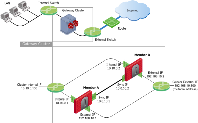
Each cluster member has three interfaces: one external interface, one internal interface, and one for synchronization. Cluster member interfaces facing in each direction are connected via a switch, router, or VLAN switch.
All cluster member interfaces facing the same direction must be in the same network. For example, there must not be a router between cluster members.
The Security Management Server can be located anywhere, and should be routable to either the internal or external cluster addresses.
The following sections present ClusterXL configuration concepts shown in the example.
Defining the Cluster Member IP Addresses
The guidelines for configuring each cluster member machine are as follows:
All machines within the cluster must have at least three interfaces:
All interfaces pointing in a certain direction must be on the same network.
For example, in the previous illustration, there are two cluster members, Member_A and Member_B. Each has an interface with an IP address facing the Internet through a hub or a switch. This is the External interface with IP address 192.168.10.1 on Member_A and 192.168.10.2 on Member_B, and is the interface that the cluster external interface sees.
Defining the Cluster Virtual IP Addresses
In the previous illustration, the IP address of the cluster is 192.168.10.100.
The cluster has one external virtual IP address and one internal virtual IP address. The external IP address is 192.168.10.100, and the internal IP address is 10.10.0.100.
The Synchronization Network
State Synchronization between cluster members ensures that if there is a failover, connections that were handled by the failed machine will be maintained. The synchronization network is used to pass connection synchronization and other state information between cluster members. This network therefore carries all the most sensitive security policy information in the organization, and so it is important to make sure the network is secure. It is possible to define more than one synchronization network for backup purposes.
To secure the synchronization interfaces, they should be directly connected by a cross cable, or in a cluster with three or more members, use a dedicated hub or switch.
Machines in a Load Sharing cluster must be synchronized because synchronization is used in normal traffic flow. Machines in a High Availability cluster do not have to be synchronized, though if they are not, connections may be lost upon failover.
The previous illustration shows a synchronization interface with a unique IP address on each machine. 10.0.10.1 on Member_A and 10.0.10.2 on Member_B.
Configuring Cluster Addresses on Different Subnets
Only one routable IP address is required in a ClusterXL cluster, for the virtual cluster interface that faces the Internet. All cluster member physical IP addresses can be non-routable.
Configuring different subnets for the cluster IP addresses and the member addresses is useful in order to:
ClusterXL ModesIntroduction to ClusterXL Modes
ClusterXL has four working modes. This section briefly describes each mode and its relative advantages and disadvantages.
Refer to the High Availability Legacy appendix for a detailed discussion of legacy High Availability functionality. It is recommended that you use the High Availability New Mode to avoid problems with backward compatibility.
Load Sharing Multicast Mode
Load Sharing enables you to distribute network traffic between cluster members. In contrast to High Availability, where only a single member is active at any given time, all cluster members in a Load Sharing solution are active, and the cluster is responsible for assigning a portion of the traffic to each member. This assignment is the task of a decision function, which examines each packet going through the cluster, and determines which member should handle it. Thus, a Load Sharing cluster utilizes all cluster members, which usually leads to an increase in its total throughput.
It is important to understand that ClusterXL Load Sharing, when combined with State Synchronization, provides a full High Availability solution as well. When all cluster members are active, traffic is evenly distributed between the machines. In case of a failover event, caused by a problem in one of the members, the processing of all connections handled by the faulty machine is immediately taken over by the other members.
ClusterXL offers two separate Load Sharing solutions: Multicast and Unicast. The two modes differ in the way members receive the packets sent to the cluster. This section describes the Multicast mode.
The Multicast mechanism, which is provided by the Ethernet network layer, allows several interfaces to be associated with a single physical (MAC) address. Unlike Broadcast, which binds all interfaces in the same subnet to a single address, Multicast enables grouping within networks. This means that it is possible to select the interfaces within a single subnet that will receive packets sent to a given MAC address.
ClusterXL uses the Multicast mechanism to associate the virtual cluster IP addresses with all cluster members. By binding these IP addresses to a Multicast MAC address, it ensures that all packets sent to the cluster, acting as a gateway, will reach all members in the cluster. Each member then decides whether it should process the packets or not. This decision is the core of the Load Sharing mechanism: it has to assure that at least one member will process each packet (so that traffic is not blocked), and that no two members will handle the same packets (so that traffic is not duplicated).
An additional requirement of the decision function is to route each connection through a single gateway, to ensure that packets that belong to a single connection will be processed by the same member. Unfortunately, this requirement cannot always be enforced, and in some cases, packets of the same connection will be handled by different members. ClusterXL handles these situations using its State Synchronization mechanism, which mirrors connections on all cluster members.
Example
This scenario describes a user logging from the Internet to a Web server behind the Firewall cluster that is configured in Load Sharing Multicast mode.
Load Sharing Unicast Mode
Load Sharing Unicast mode provides a Load Sharing solution adapted to environments where Multicast Ethernet cannot operate. In this mode a single cluster member, referred to as Pivot, is associated with the cluster's virtual IP addresses, and is thus the only member to receive packets sent to the cluster. The pivot is then responsible for propagating the packets to other cluster members, creating a Load Sharing mechanism. Distribution is performed by applying a decision function on each packet, the same way it is done in Load Sharing Multicast mode. The difference is that only one member performs this selection: any non-pivot member that receives a forwarded packet will handle it, without applying the decision function. Note that non-pivot members are still considered as "active", since they perform routing and Firewall tasks on a share of the traffic (although they do not perform decisions.).
Even though the pivot member is responsible for the decision process, it still acts as a Security Gateway that processes packets (for example, the decision it makes can be to handle a packet on the local machine). However, since its additional tasks can be time consuming, it is usually assigned a smaller share of the total load.
When a failover event occurs in a non-pivot member, its handled connections are redistributed between active cluster members, providing the same High Availability capabilities of New High Availability and Load Sharing Multicast. When the pivot member encounters a problem, a regular failover event occurs, and, in addition, another member assumes the role of the new pivot. The pivot member is always the active member with the highest priority. This means that when a former pivot recuperates, it will retain its previous role.
Example
In this scenario, we use a Load Sharing Unicast cluster as the gateway between the user's computer and the Web server.
High Availability Mode
The High Availability Mode provides basic High-Availability capabilities in a cluster environment. This means that the cluster can provide Firewall services even when it encounters a problem, which on a stand-alone gateway would have resulted in a complete loss of connectivity. When combined with Check Point's State Synchronization, ClusterXL High Availability can maintain connections through failover events, in a user-transparent manner, allowing a flawless connectivity experience. Thus, High-Availability provides a backup mechanism, which organizations can use to reduce the risk of unexpected downtime, especially in a mission-critical environment (such as one involving money transactions over the Internet.)
To achieve this purpose, ClusterXL's New High Availability mode designates one of the cluster members as the active machine, while the other members remain in stand-by mode. The cluster's virtual IP addresses are associated with the physical network interfaces of the active machine (by matching the virtual IP address with the unique MAC address of the appropriate interface). Thus, all traffic directed at the cluster is actually routed (and filtered) by the active member. The role of each cluster member is chosen according to its priority, with the active member being the one with the highest ranking. Member priorities correspond to the order in which they appear in the Cluster Members page of the Gateway Cluster Properties window. The top-most member has the highest priority. You can modify this ranking at any time.
In addition to its role as a Firewall gateway, the active member is also responsible for informing the stand-by members of any changes to its connection and state tables, keeping these members up-to-date with the current traffic passing through the cluster.
Whenever the cluster detects a problem in the active member that is severe enough to cause a failover event, it passes the role of the active member to one of the standby machines (the member with the currently highest priority). If State Synchronization is applied, any open connections are recognized by the new active machine, and are handled according to their last known state. Upon the recovery of a member with a higher priority, the role of the active machine may or may not be switched back to that member, depending on the user's configuration.
It is important to note that the cluster may encounter problems in standby machines as well. In this case, these machines are not considered for the role of active members, in the event of a failover.
Example
This scenario describes a user logging from the Internet to a Web server behind the Firewall cluster.
Mode Comparison Table
This table summarizes the similarities and differences between the ClusterXL modes.
ClusterXL Mode comparison table
FailoverWhat is a Failover?
A failover occurs when a Gateway is no longer able to perform its designated functions. When this happens another Gateway in the cluster assumes the failed Gateway's responsibilities.
In a Load Sharing configuration, if one Security Gateway in a cluster of gateways goes down, its connections are distributed among the remaining Gateways. All gateways in a Load Sharing configuration are synchronized, so no connections are interrupted.
In a High Availability configuration, if one Gateway in a synchronized cluster goes down, another Gateway becomes active and "takes over" the connections of the failed Gateway. If you do not use State Synchronization, existing connections are closed when failover occurs, although new connections can be opened.
To tell each cluster member that the other gateways are alive and functioning, the ClusterXL Cluster Control Protocol maintains a heart beat between cluster members. If a certain predetermined time has elapsed and no message is received from a cluster member, it is assumed that the cluster member is down and a failover occurs. At this point another cluster member automatically assumes the responsibilities of the failed cluster member.
It should be noted that a cluster machine may still be operational but if any of the above checks fail in the cluster, then the faulty member initiates the failover because it has determined that it can no longer function as a cluster member.
Note that more than one cluster member may encounter a problem that will result in a failover event. In cases where all cluster members encounter such problems, ClusterXL will try to choose a single member to continue operating. The state of the chosen member will be reported as Active Attention. This situation lasts until another member fully recovers. For example, if a cross cable connecting the cluster members malfunctions, both members will detect an interface problem. One of them will change to the Downstate, and the other to Active Attention.
When Does a Failover Occur?
A failover takes place when one of the following occurs on the active cluster member:
What Happens When a Gateway Recovers?
In a Load Sharing configuration, when the failed Gateway in a cluster recovers, all connections are redistributed among all active members.
In a High Availability configuration, when the failed Gateway in a cluster recovers, the recovery method depends on the configured cluster setting. The options are:
How a Recovered Cluster Member Obtains the Security Policy
The administrator installs the security policy on the cluster rather than separately on individual cluster members. The policy is automatically installed on all cluster members. The policy is sent to the IP address defined in the General Properties page of the cluster member object.
When a failed cluster member recovers, it will first try to take a policy from one of the other cluster members. The assumption is that the other cluster members have a more up to date policy. If this does not succeed, it compares its own local policy to the policy on the Security Management server. If the policy on the Security Management server is more up to date than the one on the cluster member, the policy on the Security Management server will be retrieved. If the cluster member does not have a local policy, it retrieves one from the Security Management server. This ensures that all cluster members use the same policy at any given moment.
Implementation Planning ConsiderationsHigh Availability or Load Sharing
Whether to choose a Load Sharing (Active/Active) or a High Availability (Active/Standby) configuration depends on the need and requirements of the organization. A High Availability gateway cluster ensures fail-safe connectivity for the organization. Load Sharing provides the additional benefit of increasing performance.
Choosing the Load Sharing Mode
Load Sharing Multicast mode is an efficient way to handle a high load because the load is distributed optimally between all cluster members. However, not all routers can be used for Load Sharing Multicast mode. Load Sharing Multicast mode associates a multicast MAC with each unicast cluster IP address. This ensures that traffic destined for the cluster is received by all members. The ARP replies sent by a cluster member will therefore indicate that the cluster IP address is reachable via a multicast MAC address.
Some routing devices will not accept such ARP replies. For some routers, adding a static ARP entry for the cluster IP address on the routing device will solve the issue. Other routers will not accept this type of static ARP entry.
Another consideration is whether your deployment includes routing devices with interfaces operating in promiscuous mode. If on the same network segment there exists two such routers and a ClusterXL gateway in Load Sharing Multicast mode, traffic destined for the cluster that is generated by one of the routers could also be processed by the other router.
For these cases, use Load Sharing Unicast mode, which does not require the use of multicast for the cluster addresses.
IP Address Migration
If you wish to provide High Availability or Load Sharing to an existing single gateway configuration, it is recommended to take the existing IP addresses from the current gateway, and make these the cluster addresses (cluster virtual addresses), when feasible. Doing so will avoid altering current IPSec endpoint identities, as well keep Hide NAT configurations the same in many cases.
Hardware Requirements, Compatibility and Cisco ExampleClusterXL Hardware Requirements
The Gateway Cluster is usually located in an environment having other networking devices such as switches and routers. These devices and the Gateways must interact to assure network connectivity. This section outlines the requirements imposed by ClusterXL on surrounding networking equipment.
HA New and Load Sharing Unicast Modes
Multicast mode is the default Cluster Control Protocol (CCP) mode in High Availability New Mode and Load Sharing Unicast Mode (and also Load Sharing Multicast Mode).
When using CCP in multicast mode, configure the following settings on the switch.
Switch Setting for High Availability New Mode and Load Sharing
Configure the following settings on the router:
Router Setting for High Availability New Mode and Load Sharing Unicast Mode
Virtual MAC mode - VMAC
When the ClusterXL product is configured in HA mode or load-sharing unicast mode (not multicast) a single cluster member is associated with the Cluster's Virtual IP address. In a High Availability environment, the single member is the active member. In a load-sharing environment, the single member is the pivot.
After fail-over, the new active member (or pivot member) broadcasts a series of Gratuitous ARP Requests (G-ARPs). The G-ARPS associate the Virtual IP address of the cluster with the physical MAC address of the new active member or the new pivot. When this happens:
To minimize possible traffic outage during a fail-over, configure the cluster to use a virtual MAC address (VMAC).
By enabling Virtual MAC in ClusterXL High Availability mode, or Load Sharing Unicast mode, all cluster members associate the same Virtual MAC address with all Cluster Virtual Interfaces and the Virtual IP address. In Virtual MAC mode, the VMAC that is advertised by the cluster members (through G-ARP Requests) keeps the real MAC address of each member and adds a Virtual MAC address on top of it.
(For local connections and sync connections, the real MAC address of each member is still associated with its real IP address.)
VMAC failover time is shorter than a failover that involves a physical MAC address.
To configure VMAC Mode using SmartDashboard (R76 and higher):
To configure VMAC Mode using the command line:
Set the value of global kernel parameter
fwha_vmac_global_param_enabled.
For more on VMAC mode, see: sk50840
To set the VMAC mode value permanently, see the sk on changing kernel global parameters: sk26202
Load Sharing Multicast Mode
When working in Load Sharing Multicast mode, the switch settings are as follows:
Switch Configuration for Load Sharing Multicast Mode
When working in Load Sharing Multicast mode, the router must support sending unicast IP packets with Multicast MAC addresses. This is required so that all cluster members will receive the data packets.
The following settings may need to be configured in order to support this mode, depending on the model of the router:
Router Configuration for Load Sharing Multicast Mode
ClusterXL Hardware Compatibility
The following routers and switches are known to be compatible for all ClusterXL modes:
Routers
Routing Switch
Switches
Example Configuration of a Cisco Catalyst Routing Switch
The following example shows how to perform the configuration commands needed to support ClusterXL on a Cisco Catalyst 6500 Series routing switch. For more details, or instructions for other networking devices, please refer to the device vendor documentation.
Disabling IGMP Snooping
To disable IGMP snooping run:
no ip igmp snoopingDefining Static Cam Entries
To add a permanent multicast entry to the table for module 1, port 1, and module 2, ports 1, 3, and 8 through 12:
To determine the MAC addresses which needs to be set:
Disabling Multicast Limits
To disable multicast limits run:
no storm-control multicast levelConfiguring a Static ARP Entry on the Router
To define a static ARP entry:
Disabling Multicast Packets from Reaching the Router
To prevent multicast packets from reaching the router:
Check Point Software CompatibilityOperating System Compatibility
The operating systems listed in the table below are supported by ClusterXL, with the limitations listed in the notes below. For details on the supported versions of these operating systems, refer to the R76 Release Notes.
ClusterXL Operating System Compatibility
Notes
1. VLANs are supported on all interfaces.
ClusterXL Compatibility (Excluding IPS)
The following table and accompanying notes present ClusterXL Load Sharing and High Availability compatibility for OPSEC Certified cluster products. Some Check Point products and features are not supported or are only partially supported (as detailed in the footnotes) for use with ClusterXL.
Products and features that are not fully supported with ClusterXL
ClusterXL Compatibility with IPS
The following IPS features are supported by ClusterXL, with the limitations listed in the notes.
ClusterXL Compatibility with IPS
Footnotes
Forwarding Layer
The Forwarding Layer is a ClusterXL mechanism that allows a cluster member to pass packets to other members, after they have been locally inspected by the Firewall. This feature allows connections to be opened from a cluster member to an external host.
Packets originated by cluster members are hidden behind the cluster's virtual IP. Thus, a reply from an external host is sent to the cluster, and not directly to the source member. This can pose problems in the following situations:
If a member decides, upon the completion of the Firewall inspection process, that a packet is intended for another cluster member, it can use the Forwarding Layer to hand the packet over to that destination. This is done by sending the packet over a secured network (any subnet designated as a Synchronization network) directly to that member. It is important to use secured networks only, as encrypted packets are decrypted during the inspection process, and are forwarded as clear-text (unencrypted) data.
Packets sent on the Forwarding Layer use a special source MAC address to inform the receiving member that they have already been inspected by another Security Gateway. Thus, the receiving member can safely hand over these packets to the local Operating System, without further inspection. This process is secure, as Synchronization Networks should always be isolated from any other network (using a dedicated network).
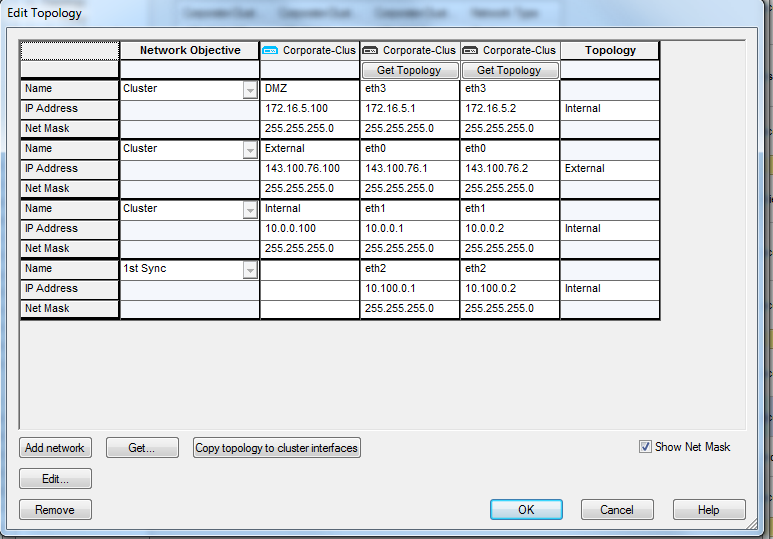
Configuring the Cluster Topology
|
Thursday, 15 February 2018
Checkpoint Firewall : High Availability and Load Sharing in ClusterXL
Subscribe to:
Post Comments (Atom)
How to set up and manage an FTP server on Windows 10
You can build your own private cloud to share and transfer files without restrictions using Windows 10's FTP server feature, and in this...

-
Watch Video - https://youtu.be/0RapEg-xcag Introduction to High Availability and Load Sharing ClusterXL is a software-based Load Sha...
-
 Watch Video - https://youtu.be/fZEy-fmjjpE Viewing Log Files Filters SmartView Tracker's filtering mechanism allows you to...
 -
Configure Active/Passive HA The following procedure shows how to configure a pair of firewalls in an active/passive deployment as depict...


ماذا سأفعل بهذا
ReplyDeletePls Type in English
Interesting, great job and a debt of gratitude is in order for sharing such a decent blog.
ReplyDeletefirewall services
Thanks a lot.
Delete