Follow Us !!

Sunday 15 March 2020

PL/SQL Cop for SonarQube 7.0 [Installation SonarQube Using PL/SQL]

We have been working on the PL/SQL Cop plugin for SonarQube. The goal was to support the most recent SonarQube versions 5.6 LTS, 6.7 LTS and 7.0. Dani was doing the heavy lifting and my job was testing and minor bug fixing. Today I can proudly announce that we were successful and that we have released the following three plugins:
  • PL/SQL Cop for SonarQube 4.5 LTS (tested with SonarQube 4.5, 4.5.7 and 5.1.2)
  • PL/SQL Cop for SonarQube 5.6 LTS (tested with SonarQube 5.6, 5.6.7, 6.0, 6.1, 6.2, 6.3, 6.3.1, 6.4, 6.5 and 6.6)
  • PL/SQL Cop for SonarQube 6.7 LTS (tested with SonarQube 6.7, 6.7.1, 6.7.2 and 7.0)
In this blog post I show how to setup a new SonarQube 7.0 server using Docker and analyze a PL/SQL project on my local machine with SonarQube Scanner. This post is a stripped down version of my Continuous Code Quality for PL/SQL with Docker post. I assume you know about Docker and have it installed on your machine.
Here is the table of content of the major steps.
  1. Create SonarQube Container
  2. Install PL/SQL Cop for SonarQube
  3. Install PL/SQL Cop (Command Line Utility)
  4. Install SonarQube Scanner
  5. Configure SonarQube
  6. Analyze a PL/SQL Project
  7. View Result in SonarQube
  8. Summary

1. Create a SonarQube Container

In this step step I create a standalone container for SonarQube 7.0 using defaults to keep it simple.

2. Install PL/SQL Cop for SonarQube

To install the current version of PL/SQL Cop for SonarQube within the “sq7” container run
The wget command will be executed within the “sq7” container. Windows user have to replace the “\” with “^” when using CMD or with “" when using PowerShell.
To load the plugin we need to restart the container.
We will complete the installation in step 5.

3. Install PL/SQL Cop (Command Line Utility)

Download PL/SQL Cop and unzip the downloaded file in a directory of your choice. I've installed it on my local machine in "/usr/local/bin/tvdcc".

4. Install SonarQube Scanner

Download SonarQube Scanner and unzip the downloaded file in a directory of your choice. I've installed it on my local machine in "/usr/local/opt/sonar-scanner".


5. Configure SonarQube 7.0

Open "http://localhost:9000" in your web browser and log in with username "admin" and password "admin".
SonarQube asks you to provide a token name. Enter "cop" and  press 
"Generate" and then "Continue" on the next page. Then the token name and the token will be shown on the upper right corner of the screen as follows:


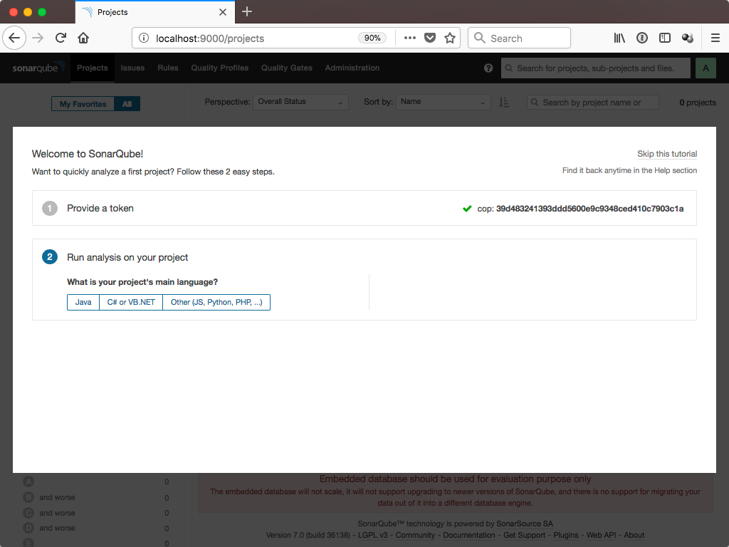
Copy your token text (39d483241393ddd5600e9c9348ced410c7903c1a) to the clipboard and store it somewhere. We will need it in step 6. Press "Skip this tutorial" in the upper right corner.

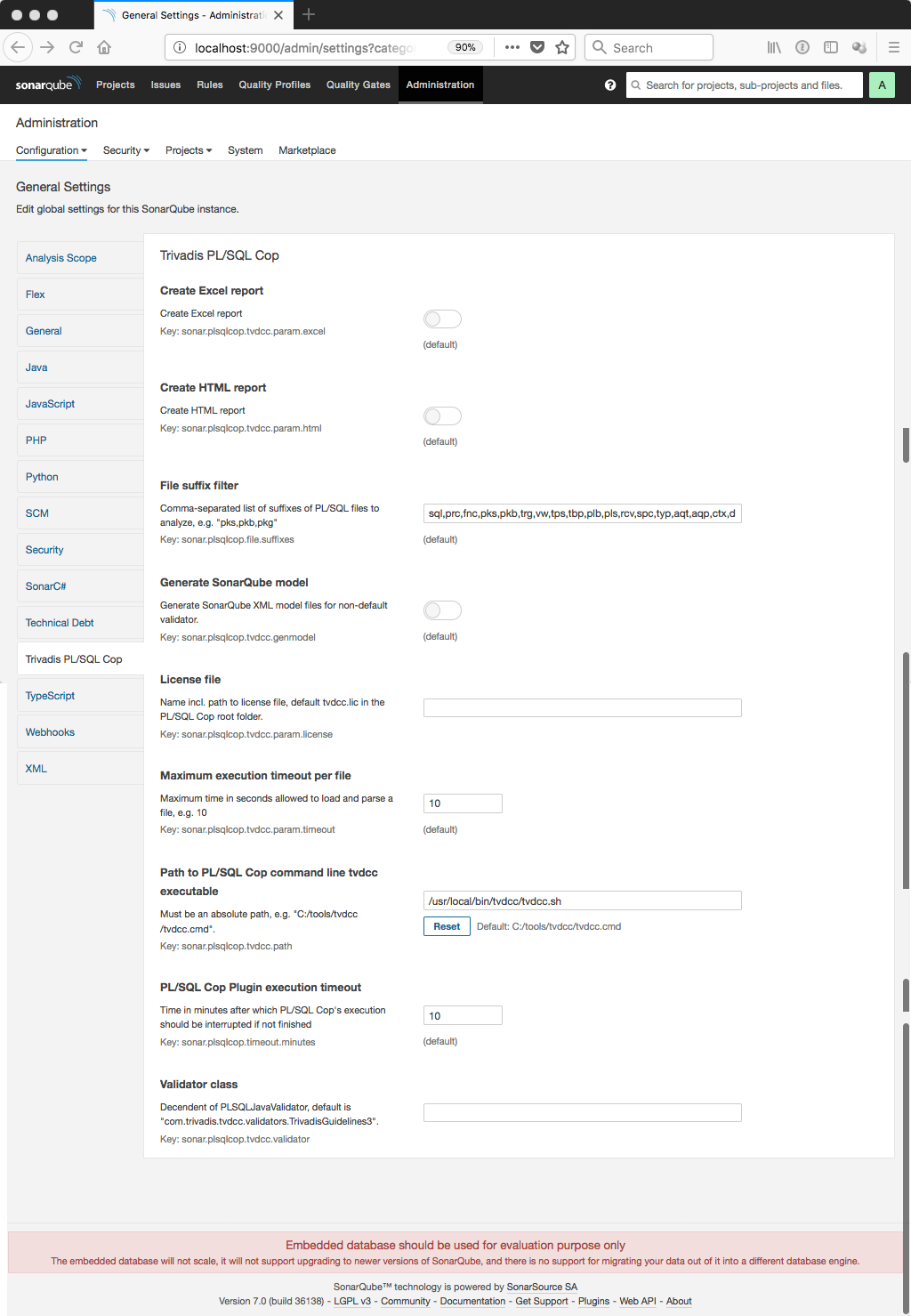
Click on "Administration" and the Category "Trivadis PL/SQL Cop" and change the "Path to PL/SQL Cop command line tvdcc executable" to the path according step 3. In may case this is "/usr/local/bin/tvdcc/tvdcc.sh". Press "Save" and you are done.

6. Analyze a PL/SQL Project

Create a temporary directory (in my case "/Users/phs/demo" and type the following
This will clone the plscope-utils git repository. If you do not have Git installed you may download the repository as zip file and extract it.
Run the following command to analyze the PL/SQL packages of this project:
Windows user have to replace the "\" with "^" when using CMD or with "” when using PowerShell.

7. View Result in SonarQube

Open “http://localhost:9000” in your web browser.
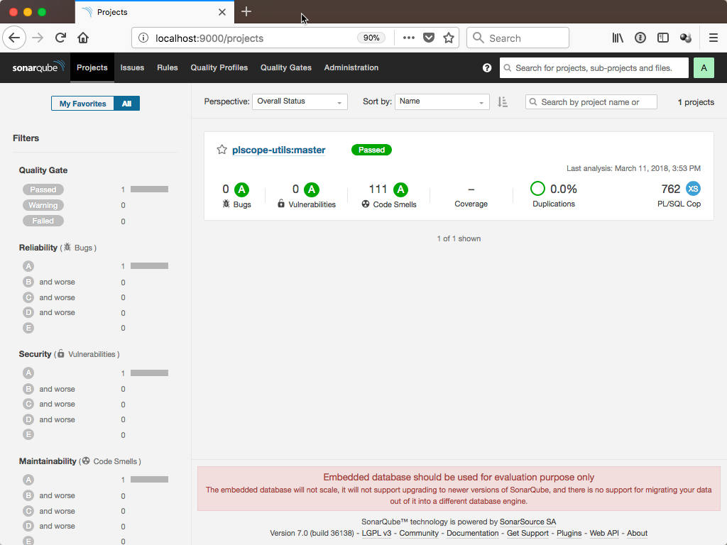
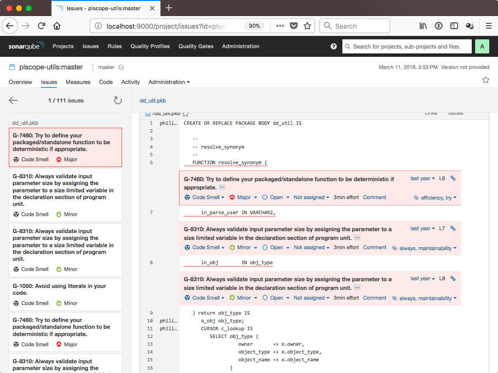
Click on “plscope-utils:master”,  select the “Issues” tab for this project and select all rules.
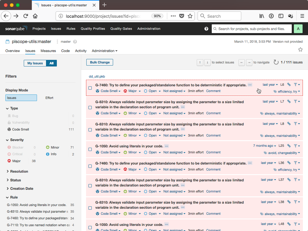
Click on an issue to see the source code line causing this issue.

8. Summary

Setting up a SonarQube 7.0 server with Docker is no big deal. Installing the PL/SQL Cop plugin is simple as well. However, I have only shown the minimum configuration. For real projects you will spend some time to configure your quality profiles and quality gates. A CI environment might help you to implement a fast quality feedback loop.


Sunday 8 March 2020

How Gateway Router Propagates and Injects a Default Route


This tutorial explains how to configure a gateway router to inject a default route in routing through a practical example in the Packet Tracer. Learn how to configure, propagate, and inject a static default route.
When a router receives a packet on its interface, the router reads the destination address of the packet and finds that destination address in the routing table. If an entry for the destination network address is available in the routing table, the router forwards the packet from the interface that is associated with the destination network in the entry.
If an entry for the destination network address is not available in the routing table, the router forwards the packet from the default gateway. In other words, a default route allows a router to forward packets those destination network addresses are not available in the routing table.
A router forwards an incoming packet from the default route only when no route is available for that packet in the routing table. This default behavior allows us to configure a default route for an external network without interfering with the existing routes of the internal network.

LAB Setup

Create a packet tracer LAB as shown in the following image and assign IP configuration.
practice lab for gateway router
Configure RIPv2 routing on all three routers (A, B, and C) as shown in the following figure.
configure rip routing
To verify the setup, test the connectivity between PC5 and PC1.
test connectivity
Currently, this network is not connected to the Internet. Our objective is to connect this network to the Internet without making any change in existing routes and routing.
Usually, ISPs offer Internet connection through a DSL modem. A DSL modem is the combination of a router and an Ethernet switch. The router of the DSL modem connects the local network to the ISP office. The Ethernet switch of the DSL modem connects the local network to the router of the DSL modem.
To simulate the DSL modem, connect a router on the Ethernet port of the router A and assign IP configuration as shown in the following image.
adding dsm modem to network
If you cannot replicate this LAB in your packet tracer, you can download the following pre-configured practice LAB.

Configuring and injecting a default route

Since we have connected the DSL modem (ISP router) to the Fa0/1 Ethernet port of router A, this router will now act as a gateway router. To configure the default routing on this router in such a way that it forwards only internet traffic from the Fa0/1 interface, run the following commands from the global configuration mode.
Router(config)#ip route 0.0.0.0 0.0.0.0 192.168.1.1
Router(config)#router rip
Router(config-router)#default-information originate
The IP address 192.168.1.1 is configured on the Fa0/1 interface of the ISP router and this interface is directly connected to the Fa0/0 interface of the router A. The first command configures a default route to forward packets from the Fa0/0 interface.
The second command changes the global configuration mode into the RIP-routing configuration mode.
The third command instructs the RIP-routing protocol to advertise/propagate the default route through its broadcasts.
configure default routing
To verify that the default route is properly propagated and injected in routing tables of all routers, use the "show ip route" privileged-exec mode command.
show ip route command output
As you can see in the above output, the default route has been successfully injected into the routing table of all routers. Now, any packet that is not intended for the internal network will be sent to the gateway router and the gateway router will forward that packet from the Fa0/1 interface to the ISP router.
To verify this setup, access a website that is hosted on the IP 150.0.0.1.
To simulate this scenario, open PC5's traffic generator and make the settings as shown in the following figure and click the Send button.
traffic generator
Once the send button is clicked, PC5 continuously sends HTTP packets to the destination IP 150.0.0.1. If these packets reach the ISP router, our setup will be verified.
To view where all packets reach, click the Simulation button available in the bottom-right corner of the packet tracer. In the Simulation pane, click the Start button.
http traffic testing
As you can see in the output above, packets sent to the Internet host have reached the ISP router. This verifies that the network’s PCs can access the Internet through the configured default route.
To verify that we have not messed up existing routes, let's do another test. Open PC5’s traffic generator again and click the Stop button to stop the ongoing testing.
Now, adjust settings as given in the following image, and click the Send button to send the FTP packets to PC1.
ftp traffic generator setting
If the packets reach PC1, it will confirm that only packets that are intended for an external network will be sent to the ISP router. If packets are intended for an internal device, they will not be forwarded to the ISP router.
ftp traffic to internal network testing
In case if you don’t get a similar output, download the following configured LAB and compare your LAB to detect misconfiguration.

How to set up and manage an FTP server on Windows 10

You can build your own private cloud to share and transfer files without restrictions using Windows 10's FTP server feature, and in this...